Effective water management forms the foundation of any successful civil engineering project, whether you're constructing a commercial car park, installing a residential driveway, or developing public realm infrastructure. Underground drainage installation represents a critical component of this process, protecting structures from water damage whilst ensuring compliance with current building regulations. Getting the installation right from the outset prevents costly remediation work and ensures the longevity of your investment.
Understanding Underground Drainage Systems
Underground drainage systems serve multiple purposes across both commercial and domestic applications. They channel surface water away from buildings, roads, and paved areas, preventing flooding and structural damage. These systems also manage foul water from properties, directing it safely to treatment facilities or septic tanks.
The two primary types of underground drainage are surface water drainage and foul water drainage. Surface water systems collect rainwater from roofs, driveways, and paved areas, whilst foul systems handle wastewater from kitchens, bathrooms, and toilets. In modern developments, these systems must remain separate to comply with UK building regulations and environmental standards.
Key components of underground drainage systems include:
- Drainage pipes (typically 110mm for domestic, 160mm for commercial applications)
- Inspection chambers and manholes for maintenance access
- Gullies and surface water inlets
- Soakaways or connections to main sewers
- Rodding eyes for clearing blockages
Material selection significantly impacts system performance and longevity. PVC-U pipes dominate the market due to their corrosion resistance, lightweight properties, and ease of installation. Clay pipes remain popular for foul drainage, particularly in conservation areas, whilst concrete pipes suit heavy-duty commercial applications.
Planning Your Underground Drainage Installation

Thorough planning prevents installation failures and regulatory issues. Begin with a comprehensive site survey identifying existing drainage infrastructure, ground conditions, and potential obstacles. Understanding soil composition determines bedding requirements and influences pipe material selection.
Calculate drainage requirements based on the area to be drained. For surface water, multiply the paved area by expected rainfall intensity. Commercial projects like drive-through restaurants require significantly higher capacity than residential driveways. Factor in future development when sizing systems, as undersized drainage causes persistent problems.
Regulatory Compliance and Building Control
Building regulations approval is mandatory for most underground drainage work in the UK. Part H of the Building Regulations governs drainage and waste disposal, specifying minimum standards for pipe gradients, materials, and installation methods. Installing underground drainage systems requires adherence to these standards to receive certification.
| Regulation Aspect | Requirement | Application |
|---|---|---|
| Minimum gradient | 1:40 for 100mm pipes | Ensures self-cleansing flow |
| Pipe bedding | 100mm granular bedding | Supports pipes and prevents settlement |
| Inspection chambers | Every 45m on straight runs | Enables maintenance access |
| Testing | Air or water test | Confirms system integrity |
Contact your local authority's building control department before commencing work. They'll specify inspection points throughout the installation process. For commercial services involving public highways or adoptable infrastructure, additional approvals from highways authorities may be necessary.
Site Preparation and Excavation
Safe excavation forms the cornerstone of successful underground drainage installation. Mark out drainage routes using string lines and pegs, ensuring clear visibility of the proposed system layout. Check for existing utilities by consulting drawings and using cable detection equipment. Striking existing services causes project delays, safety hazards, and significant repair costs.
Trench width depends on pipe diameter and installation depth. As a general rule, trenches should be 300mm wider than the pipe diameter to allow adequate working space. For 110mm pipes, a 450mm wide trench suffices for most situations. Larger bore drainage systems require proportionally wider excavations.
Excavation depth must account for several factors. Pipes require sufficient cover to prevent damage from traffic loads, typically 900mm beneath driveways and 1200mm under highways. The gradient for self-cleansing flow adds to this depth along the drainage run. Always excavate slightly deeper than the final level to accommodate bedding material.
Essential excavation safety measures include:
- Shoring or battering trench sides when exceeding 1.2m depth
- Installing barriers around open excavations
- Providing safe access and egress points
- Removing excavated material from trench edges
- Monitoring groundwater levels and pumping when necessary
Pipe Installation Techniques
Proper pipe laying ensures system longevity and performance. Begin by preparing the trench bottom, removing stones and creating a uniform surface. Install 100mm of granular bedding material, typically 10mm single-sized gravel or pea shingle. This bedding supports the pipe barrel and distributes loads evenly.
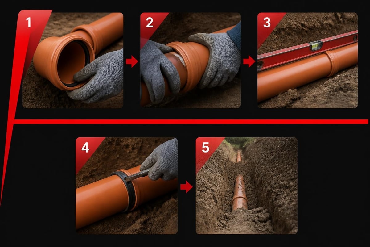
Lay pipes from the lowest point upward, working against the flow direction. This approach allows water to drain from the trench during installation. Each pipe length should be checked for gradient using a spirit level and straight edge. Maintaining consistent falls prevents ponding and ensures self-cleansing velocities.
Achieving Correct Gradients
Gradient calculation directly impacts drainage performance. The minimum gradient for 110mm underground drainage sits at 1:40, meaning a 25mm fall per metre of pipe. Commercial applications often benefit from steeper gradients of 1:60 to 1:80, providing additional insurance against blockages.
Calculate the total fall required by multiplying pipe length by the gradient ratio. For a 20-metre run at 1:40 gradient, the fall equals 500mm. Mark this on profile boards at each end of the trench, using string lines to guide installation. Check multiple points along the run rather than relying on end measurements alone.
Modern laser levels streamline gradient checking on longer runs. Position the laser at the correct angle and verify pipe positioning against the beam. This technology proves particularly valuable on commercial projects where precision directly affects system capacity and performance.
Connecting to Inspection Chambers
Inspection chambers provide essential access for maintenance and CCTV surveys. Position chambers at changes of direction, changes of gradient, and junctions where multiple pipes converge. Maximum spacing between chambers on straight runs should not exceed 45 metres for pipes up to 150mm diameter.
Installing chambers requires careful attention to incoming and outgoing pipe levels. Benching within the chamber directs flow smoothly between pipes, preventing deposition of solids. Pre-formed plastic chambers simplify this process, offering integral benching and multiple inlet positions.
Chamber installation checklist:
- Excavate chamber position to required depth
- Install base section on compacted granular foundation
- Connect incoming and outgoing pipes using flexible couplings
- Build up chamber sections to required height
- Install frame and cover to finished surface level
- Seal joints between chamber sections
For domestic services like patio drainage, smaller mini-chambers or rodding eyes may suffice. These compact units provide access without the footprint of traditional inspection chambers, making them ideal for confined spaces or landscaped areas.
Backfilling and Compaction
Backfilling protects installed pipes whilst supporting the ground above. Never use excavated material for initial backfilling around pipes. Instead, employ selected granular material up to 300mm above the pipe crown. This protective surround cushions the pipe against point loads and prevents damage from settlement.
Backfill in layers not exceeding 150mm thickness when compacted. Hand-compact material immediately around pipes to avoid displacement. Once sufficient cover exists, mechanical compaction becomes appropriate. Plate compactors work well for shallow trenches, whilst roller compactors suit larger commercial installations.
| Backfill Zone | Material Type | Compaction Method |
|---|---|---|
| Pipe surround (0-150mm above crown) | 10mm gravel | Hand compaction |
| Initial backfill (150-300mm above crown) | Selected granular | Light mechanical compaction |
| Main backfill (above 300mm) | Selected fill or excavated material | Full mechanical compaction |
| Surface restoration | Type 1 sub-base | Roller or plate compaction to specification |
Proper compaction prevents future settlement that creates dips in driveways or paved areas. For projects involving highways surfacing, achieving specified compaction levels ensures the pavement structure performs as designed. Test compaction at intervals using nuclear density gauges or plate bearing tests on larger commercial works.
Testing and Commissioning
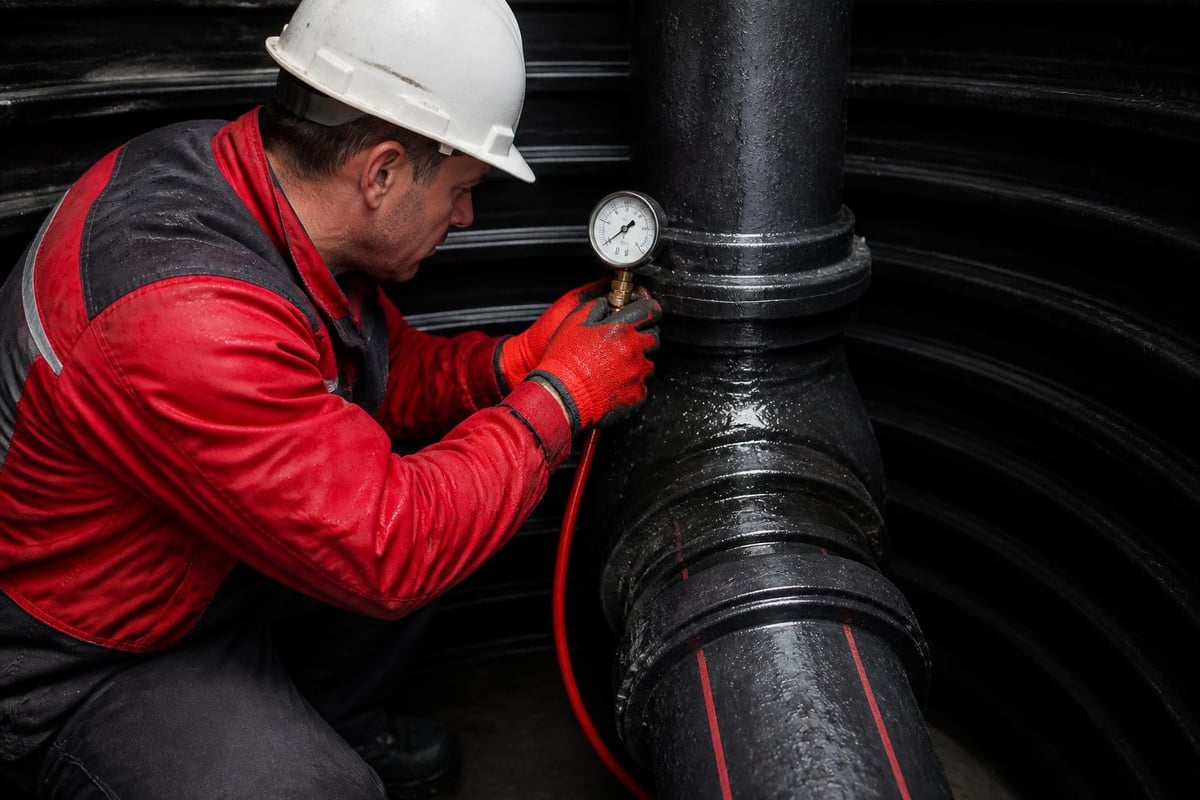
Every underground drainage installation requires testing before backfilling and commissioning. Building Control officers must witness these tests, so schedule inspections before proceeding. Two primary test methods exist: air testing and water testing.
Air testing involves sealing the pipe system and introducing compressed air to a specified pressure, typically 100mm head of water (approximately 10kPa). The system must maintain this pressure for five minutes without dropping more than 25mm head. This method quickly identifies leaks and poorly made joints.
Water testing remains the traditional approach, particularly for foul drainage. Fill the system to the top of the highest inspection chamber and maintain this level for 30 minutes. Any drop in water level indicates leakage requiring investigation and repair. Water testing proves more reliable for systems with numerous connections where air testing might produce false failures.
Common Testing Failures and Solutions
Joint failures represent the most frequent cause of test failures. Push-fit joints require proper cleaning and lubrication before assembly. Ensure socket depths are achieved fully, with visible alignment marks. Rubber seals must sit correctly in grooves without twisting or displacement.
Inspection chamber connections sometimes leak where pipes penetrate chamber walls. Use flexible couplings designed for this application rather than rigid joints. These accommodate slight movement and settlement without compromising the seal. Apply sealant to the external joint as additional insurance against groundwater ingress.
Cracked pipes occasionally occur during installation, particularly in cold weather when PVC-U becomes more brittle. Handle pipes carefully and avoid dropping them into trenches. Store materials properly on site, keeping them off the ground and protected from damage.
Connecting Surface Water Collection Points
Surface water enters the drainage system through various inlet types. Gullies serve paved areas like driveways and car parks, collecting water at low points. Proper patio drainage often incorporates linear channel drains along the property boundary, intercepting water before it reaches the building.
Downspouts from roofs require careful consideration. Direct connection to surface water drains works well, but installation must consider proper slope and outlet placement to prevent basement flooding and foundation damage. Position rodding eyes at downspout connections for clearing blockages from leaves and debris.
Selecting appropriate surface water inlets:
- Yard gullies for general paved areas (typically 110mm outlet)
- Road gullies for highways and large car parks (150mm outlet)
- Linear channel drains for long collection runs
- Roof outlets and rainwater shoes for downspout connections
Trap gullies prevent odours from combined drainage systems, using a water seal similar to internal plumbing traps. However, modern developments typically separate surface and foul water, eliminating the need for trapped gullies on surface water systems. Untrapped gullies offer better flow rates and reduced maintenance requirements.
Soakaway Design and Installation
Soakaways provide an environmentally sound method of disposing of surface water where mains drainage connections prove impractical or uneconomical. They allow water to percolate gradually into surrounding soil, reducing flood risk and recharging groundwater supplies.
Soakaway sizing depends on the area being drained and local soil percolation rates. Conduct percolation tests by digging trial holes, filling them with water, and measuring drainage rates. Clay soils with poor drainage require larger soakaways than sandy or gravelly soils. Position soakaways at least five metres from buildings to prevent foundation undermining.
Modern soakaways typically use plastic crates wrapped in geotextile membrane. These modular units provide high void ratios whilst preventing silt ingress that reduces capacity. Calculate the required volume, then stack crates to achieve the necessary storage. Wrap the assembly completely before backfilling with clean stone or excavated material.
Long-Term Maintenance Considerations
Well-installed underground drainage systems require minimal maintenance, but planning for future access prevents problems. Record the location of all inspection chambers, rodding eyes, and pipe runs. Simple drawings showing measurements from permanent features like building corners enable future contractors to locate infrastructure quickly.
Install inspection chambers generously throughout the system. The additional cost proves minimal compared with excavating to clear blockages when no access exists. Position chambers at logical points where blockages might occur, such as downstream of gullies serving areas with heavy leaf fall.
Consider installing clean-out access points where downspouts connect to underground drainage. These simple additions allow periodic flushing of the system, removing accumulated debris before it causes blockages. On commercial developments like drive-through facilities, regular maintenance prevents service disruptions during peak trading periods.
Professional Installation Standards
Achieving professional results requires attention to detail throughout the installation process. Use proper materials from reputable manufacturers, ensuring all components comply with relevant British Standards. Cheap alternatives may save money initially but often fail prematurely, creating expensive remediation work.
Follow manufacturer's installation guidelines precisely. Installation guides for underground drainage provide specific instructions for their products, covering everything from joint assembly to bedding requirements. Deviating from these specifications may void warranties and compromise performance.
Maintain photographic records throughout the installation process. Images of pipe layouts before backfilling prove invaluable for future maintenance and extensions. Building Control officers appreciate comprehensive documentation, expediting approvals and certification.
| Installation Phase | Key Quality Checks | Documentation Required |
|---|---|---|
| Excavation | Trench width, depth, safety measures | Site photos, utility clearance records |
| Bedding | Material type, thickness, compaction | Material certification, compaction tests |
| Pipe laying | Gradient, alignment, joint assembly | As-built drawings, level measurements |
| Testing | Pressure/water test results | Witnessed test certificates |
| Backfilling | Material selection, compaction | Compaction test results, surface levels |
Materials and Equipment Selection
Selecting appropriate materials affects both installation efficiency and long-term performance. PVC-U pipes dominate residential and light commercial applications due to their cost-effectiveness and ease of handling. Following installation guidelines ensures these systems perform reliably for decades.
Heavier-duty applications benefit from thicker-walled pipes or alternative materials. Highways work requires pipes capable of withstanding significant traffic loads without deflection or failure. Your civil engineering contractor should specify materials appropriate to the application, considering both immediate loading and future traffic growth.
Essential materials for underground drainage installation:
- Drainage pipes (110mm or 160mm depending on application)
- Couplings, bends, and junctions
- Inspection chambers complete with frames and covers
- Bedding and surround material (10mm gravel)
- Backfill material (Type 1 or selected granular)
- Lubricant for push-fit joints
Equipment requirements vary with project scale. Residential installations often manage with basic hand tools and a mini-excavator. Commercial projects demand larger machinery, laser levels for gradient control, and compaction equipment for proper backfilling. Hiring specialist equipment for short periods often proves more economical than purchasing.
Successful underground drainage installation combines careful planning, quality materials, and precise execution to create systems that protect property and infrastructure for generations. Whether you're developing a commercial site or enhancing residential property, professional installation ensures compliance with regulations whilst delivering reliable long-term performance. At JRG Civils, our civil engineering expertise spans both commercial developments and domestic projects across the UK, bringing the same attention to detail and commitment to excellence that has made us the trusted choice for major franchise installations and private residential work alike. Contact our team to discuss your drainage requirements and discover how our professional approach delivers results that stand the test of time.