
The foundation of any successful bridge project lies beneath what most observers see. While elegant spans and impressive decks capture attention, the bridge substructure performs the critical engineering work of transferring all loads safely into the ground. Understanding these hidden components proves essential for civil engineers, contractors, and project managers involved in infrastructure development. From commercial developments requiring access bridges to major highway projects, the principles governing substructure design remain consistent and crucial.
Understanding Bridge Substructure Components
The bridge substructure encompasses all structural elements positioned below the bridge deck that support and stabilise the entire structure. These components work together as an integrated system, each playing a specific role in load distribution and structural stability.
Primary substructure elements include:
- Foundations (shallow or deep, depending on soil conditions)
- Abutments (end supports connecting bridge to embankments)
- Piers (intermediate supports for multi-span bridges)
- Wing walls (retaining structures adjacent to abutments)
- Pile caps (structural elements distributing loads to pile groups)
- Bearings (devices allowing controlled movement between superstructure and substructure)
The Washington State Department of Transportation provides comprehensive guidelines covering these components in detail, offering valuable insights for design professionals. Each element requires careful consideration of soil conditions, anticipated loads, environmental factors, and construction methods.
Foundation Systems
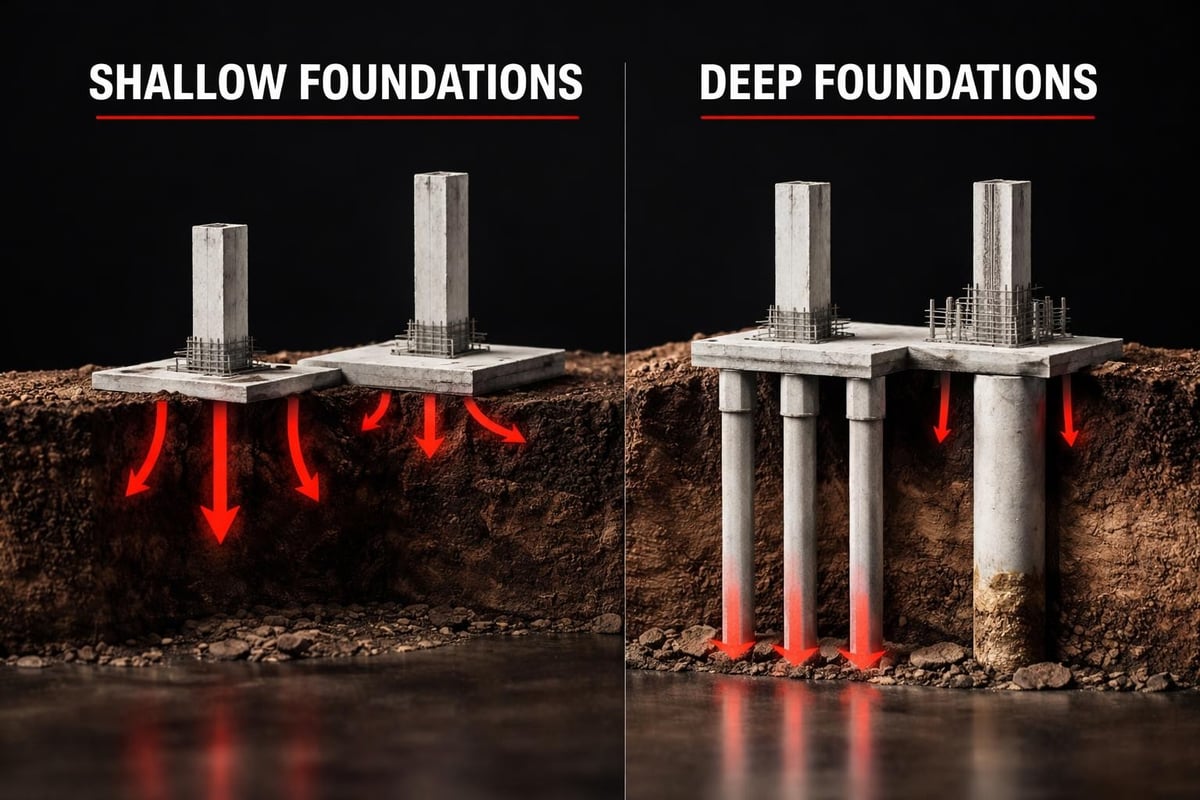
Foundation selection represents perhaps the most critical decision in bridge substructure design. The choice between shallow and deep foundations depends primarily on subsurface conditions, load magnitudes, and site-specific constraints.
Shallow foundations, including spread footings and mat foundations, prove suitable when competent bearing strata exist near the surface. These economical solutions work well for smaller bridges and favourable ground conditions. Deep foundations become necessary when surface soils cannot adequately support imposed loads or when scour potential exists.
| Foundation Type | Best Applications | Typical Depth | Key Advantages |
|---|---|---|---|
| Spread Footings | Good bearing soil near surface | 1-3 metres | Cost-effective, simple construction |
| Driven Piles | Poor surface soils, high loads | 10-40 metres | Proven capacity, versatile |
| Drilled Shafts | Variable soil, high lateral loads | 15-60 metres | Large diameter, precise placement |
| Caissons | Deep water, major structures | 20-80 metres | Handles extreme loads |
The Texas Department of Transportation’s foundation design guidance emphasises scour considerations, particularly for water crossings where erosion can undermine foundation stability over time.
Abutment Design and Construction
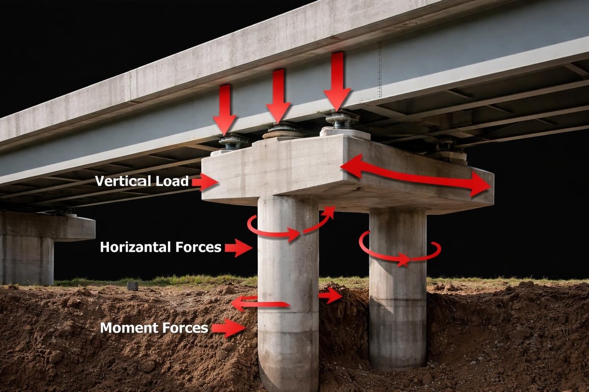
Abutments serve dual purposes: supporting bridge spans whilst retaining approach embankments. These substantial structures must resist vertical loads from the superstructure, horizontal earth pressures, and various environmental forces.
Several abutment configurations exist, each suited to specific project requirements. Gravity abutments rely on mass to resist overturning and sliding forces. Cantilever abutments use reinforced concrete walls with heel and toe projections. Stub abutments, increasingly popular for their economy, minimise structure height by incorporating approach fills.
Modern practice increasingly favours integral abutments where feasible. These designs connect the superstructure rigidly to the substructure, eliminating expansion joints and associated maintenance issues. The approach works particularly well for single-span and moderate-length multi-span bridges on stable foundations.
Key abutment design considerations include:
- Settlement analysis and differential movement accommodation
- Earth pressure calculations (at-rest, active, passive conditions)
- Drainage provision to prevent hydrostatic pressure build-up
- Wing wall configuration and stability
- Seismic performance and lateral load resistance
Construction sequencing significantly impacts abutment performance. Proper backfill placement and compaction prevent excessive lateral pressures and settlement issues. Quality control during concrete placement ensures durability and structural integrity throughout the design life.
Pier Systems and Column Design
Piers provide intermediate support for multi-span bridges, transmitting loads from the superstructure through columns to foundations below. Design flexibility allows engineers to optimise pier configurations for specific site conditions, aesthetic requirements, and structural efficiency.
Column shapes vary widely across projects. Circular columns offer excellent structural efficiency and aesthetic appeal whilst simplifying formwork. Rectangular and octagonal sections suit certain architectural contexts. Wall-type piers provide necessary stiffness for tall structures or seismic regions.
The bridge substructure must accommodate various load combinations throughout service life. Dead loads from self-weight and permanent fixtures combine with live loads from traffic, wind forces, thermal movements, and potentially seismic events. Each load case requires rigorous analysis to ensure adequate safety margins.
Material Selection for Substructure Elements
Material choice profoundly influences substructure performance, longevity, and maintenance requirements. Reinforced concrete dominates modern bridge substructure construction due to its versatility, durability, and economy. High-performance concrete mixes with appropriate admixtures resist aggressive environments encountered below ground.
Corrosion protection deserves particular attention in substructure design. Adequate concrete cover, quality aggregates, and controlled permeability protect embedded reinforcement. Epoxy-coated or stainless steel reinforcement provides additional protection in severe exposure conditions such as marine environments or areas using de-icing salts.
The Arizona Department of Transportation’s bridge design guidelines address material specifications comprehensively, ensuring structures meet demanding performance standards. For projects involving civils design, understanding these material requirements proves essential.
Bearing Systems and Movement Accommodation
Bearings form the critical interface between bridge superstructure and substructure, permitting controlled movement whilst transferring loads. These devices must accommodate thermal expansion and contraction, concrete creep and shrinkage, and various deformations whilst maintaining structural integrity.
Common bearing types include:
- Elastomeric bearings (plain and laminated rubber pads)
- Pot bearings (for heavy loads and larger movements)
- Disc bearings (high-load applications)
- Spherical bearings (multi-directional movement)
- Sliding bearings (predominantly horizontal movement)
Selection depends on load magnitude, movement requirements, rotation capacity, and maintenance considerations. Elastomeric bearings suit many moderate-span bridges due to their simplicity and reliability. More sophisticated bearing systems become necessary for longer spans, higher loads, or complex movement patterns.
The lateral restraint provisions discussed by transport authorities highlight how bearing selection integrates with overall substructure performance, particularly regarding seismic and wind resistance.
Hydraulic Considerations and Scour Protection
Water crossings introduce unique challenges requiring specialised attention during bridge substructure design. Scour, the erosion of streambed material around foundations, represents one of the leading causes of bridge failures worldwide. Understanding and mitigating scour risk proves essential for long-term structural safety.
Three scour types affect bridge substructures:
- General scour – overall lowering of the streambed across the channel
- Contraction scour – localised deepening where bridge constricts flow
- Local scour – erosion directly around piers and abutments due to flow disruption
Design approaches include founding below anticipated scour depths, providing scour protection through riprap or other armouring, and designing for structural stability even if scour occurs. Conservative scour depth predictions account for extreme flood events, debris accumulation, and long-term channel changes.
Environmental regulations increasingly influence bridge substructure work in waterways. The guidance from Fisheries and Oceans Canada demonstrates how construction activities must protect aquatic habitats whilst maintaining structural requirements. Timing restrictions, turbidity controls, and construction methodologies require careful planning.
| Scour Protection Method | Application | Durability | Installation Complexity |
|---|---|---|---|
| Riprap Armouring | Shallow to moderate depths | Good with proper sizing | Moderate |
| Gabion Mattresses | Moderate depths, erosion-prone banks | Fair to good | Moderate to high |
| Concrete Aprons | High-velocity flows | Excellent | High |
| Sheet Pile Cutoffs | Deep scour potential | Excellent | High |
Maintenance and Inspection Requirements
Regular inspection and proactive maintenance extend bridge substructure service life and ensure public safety. Unlike superstructure elements readily visible from deck level, substructure components often require special access or equipment for thorough examination.
The Missouri Department of Transportation’s maintenance guidance outlines systematic approaches to substructure care. Inspection protocols typically follow two-year cycles for routine examinations, with more frequent checks for structures in aggressive environments or showing signs of distress.
Common substructure deterioration mechanisms include:
- Concrete cracking and spalling from freeze-thaw cycles
- Reinforcement corrosion due to chloride penetration
- Alkali-aggregate reaction causing concrete expansion
- Scour and undermining of foundations
- Settlement or lateral movement from soil consolidation
- Impact damage from vehicles or waterborne debris
Early detection enables cost-effective repairs before minor issues escalate into major structural problems. Non-destructive testing methods, including ground-penetrating radar, ultrasonic testing, and electrical resistivity measurements, help assess hidden conditions without invasive investigation.

Repair and Rehabilitation Strategies
When deterioration occurs, appropriate intervention strategies depend on damage extent, structural significance, and available resources. Surface treatments address minor concrete degradation, whilst significant structural damage may require section replacement or supplemental strengthening.
Concrete repairs range from simple patching to comprehensive rehabilitation. Patch repairs work for localised damage, whilst overlays or wraps address widespread deterioration. Cathodic protection systems halt ongoing corrosion in contaminated concrete. For severe cases, jacketing existing columns or adding supplemental piers may prove necessary.
Foundation repairs present particular challenges due to access limitations and loading constraints. Underpinning extends existing foundations to greater depths. Micropile installation supplements capacity without major excavation. Grouting stabilises soils and fills voids threatening foundation integrity.
Design Optimisation and Modern Practices
Contemporary bridge substructure design benefits from advanced analytical tools and construction technologies unavailable to previous generations. Finite element analysis enables detailed stress evaluation and optimised member sizing. Building Information Modelling (BIM) facilitates coordination amongst design disciplines and construction teams.
The Delaware Department of Transportation emphasises optimisation and standardisation in substructure type selection. Standardised details reduce design time, simplify construction, and ensure proven performance. However, site-specific conditions may warrant custom solutions for optimal results.
Prefabrication increasingly features in bridge substructure construction, particularly for piers and abutment components. Shop-fabricated elements offer superior quality control, accelerated construction schedules, and reduced site disruption. Modular pier segments assembled on-site exemplify this approach.
Sustainability considerations now influence design decisions beyond traditional structural and economic factors. Locally sourced materials reduce transportation impacts. Optimised designs minimise material consumption. Durable specifications extend service life, reducing lifecycle environmental footprint. These principles align well with comprehensive civils work in the UK where environmental stewardship complements engineering excellence.
Seismic Design Considerations
Seismic events impose extreme demands on bridge substructures through intense ground shaking and potential ground displacement. Earthquake-resistant design has evolved significantly, moving from purely strength-based approaches to performance-based methodologies that accept controlled damage whilst preventing collapse.
Modern seismic design incorporates ductile detailing, allowing structural elements to deform plastically without failure. Plastic hinges form in predetermined locations, typically at column bases or tops, dissipating seismic energy through controlled yielding. Confinement reinforcement in these regions ensures ductile behaviour under cyclic loading.
Seismic design strategies include:
- Capacity design principles ensuring weak-link behaviour occurs at intended locations
- Displacement-based design accounting for anticipated deformations
- Isolation bearings reducing seismic demands transmitted to substructure
- Energy dissipation devices supplementing inherent damping
- Foundation flexibility considerations affecting overall dynamic response
Geographic location determines applicable seismic design requirements. High-seismicity regions demand rigorous analysis and detailing. Lower-risk areas may use simplified approaches whilst maintaining basic earthquake resistance.
Construction Methods and Temporary Works
Construction methodology profoundly impacts final substructure quality, project cost, and schedule. Method selection depends on access constraints, ground conditions, environmental limitations, and available equipment.
For foundations, driven pile installation offers speed and reliability when suitable equipment can access the site. Drilled shaft construction provides alternatives where vibration must be minimised or soil conditions prevent effective pile driving. Caisson construction suits major structures or challenging subsurface conditions.
Cofferdams and dewatering systems enable construction below water level. Sheet pile cofferdams create dry work areas in shallow to moderate depths. Cellular cofferdams handle deeper water and more challenging conditions. Proper design ensures stability during construction whilst protecting adjacent structures and the environment.
Quality control during construction determines long-term performance. Concrete placement requires careful attention to mix design, consolidation, and curing. Steel reinforcement must meet specified grade, size, and placement tolerances. Foundation installation verification through load testing or integrity testing confirms design assumptions.
Integration with Overall Project Success
Bridge substructure design and construction rarely occurs in isolation. Successful projects require coordination with roadway design, utility relocations, drainage systems, and environmental mitigation measures. Early engagement amongst all disciplines prevents conflicts and optimises overall solutions.
For commercial developments incorporating bridge structures, such as the drive-through facilities JRG Civils has delivered, substructure work must accommodate tight site constraints and accelerated schedules. Careful planning, efficient construction methods, and proactive coordination ensure successful outcomes.
The substructure must also consider future maintenance access. Provision for inspection equipment, adequate clearances, and accessible bearing locations facilitates lifecycle management. These seemingly minor details during design prove invaluable during the decades of service ahead.
Cost estimating for bridge substructure work requires understanding of site-specific challenges beyond standard unit prices. Subsurface conditions dramatically affect foundation costs. Environmental constraints may mandate specialised construction methods. Experienced contractors and engineers working collaboratively produce realistic budgets and achievable schedules.
Understanding bridge substructure fundamentals enables better project planning, design decisions, and construction execution across all civil engineering applications. Whether developing major infrastructure or commercial access bridges, these principles ensure safe, durable, and economical solutions. At JRG Civils, our expertise in civil engineering extends to all aspects of infrastructure development, from initial design through to meticulous construction and finishing. Based in the North East and working across the UK, we bring the same attention to detail and commitment to excellence to every project. Contact JRG Civils to discuss how our professional team can support your next infrastructure project with reliable, high-quality civil engineering services.